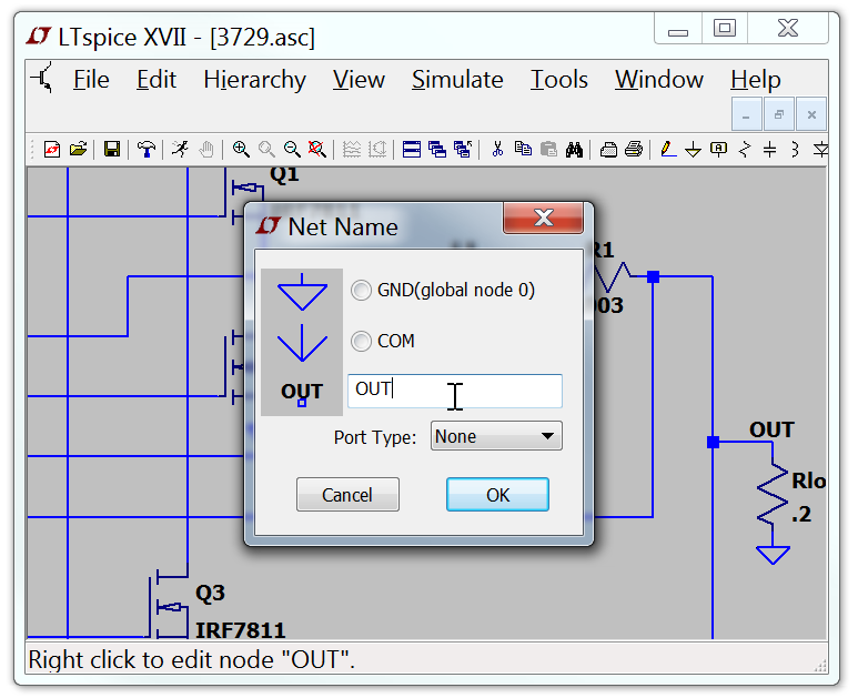
Label a Node Name
Each node in the circuit requires a unique name. You can specify the name of a node so the netlister doesn't make one up for you. Note that as you edit the schematic, automatically generated node names will of course change as the topology of the circuit changes.
Some designers prefer to label many nodes. My own preferred style, and what I recommend to others, is to not label any nodes and only plot data only via cross-probing. This is analogous to the way I scope out a circuit -- I don't label the node before attaching the scope probe. Node "0" is the circuit global ground and is drawn with a special graphical symbol instead of the name "0".
There is also a graphical symbol defined for node "COM", but this node has no special significance. That is, it's not the SPICE global common and it's not even a global node. It's just sometimes convenient to have a graphical symbol associated with a node distinct from ground.
If you give a node a name starting with the characters "$G_"; as in for example, "$G_VDD"; then that node is global no matter where the name occurs in the circuit hierarchy.

It is possible to indicate that a node is a port of type input, output, or bi-directional. These port types will be drawn differently but have no significance to the netlister. Indicating a port type can make circuit more readable. Global nodes are also drawn differently in that a box is drawn around the name.
